当前位置:首 页 --> 方案设计
TIDA-00281汽车48V 1kW马达驱动参考设计
发布时间:2016/6/21 13:26:00 来源:
TI公司的TIDA-00281是采用UCC27201A-Q1高频N沟MOSFET驱动器的汽车48V 1kW马达驱动参考设计,能处理高达30A的电流,包括和C2000 LaunchPad连接的模拟电路,不需要位置传感器就能控制三相无刷直流马达(BLDC),从48V电池系统供电,具有过压,欠压,超温,过流和瞬时故障保护.本文介绍了UCC27201A-Q1主要特性,功能框图,应用电路图以及TIDA-00281汽车48V 1kW BLDC马达驱动参考设计主要特性,系统指标,应用框图,电路图和材料清单以及pcb设计图.
The UCC27201A-Q1 high frequency N-Channel MOSFET driver includes a 120-V bootstrap diode and high-side/low-side driver with independent inputs for maximum control flexibility. This allows for N-Channel MOSFET control in half-bridge, full-bridge, two-switch forward and active clamp forward converters. The low-side and the high-side gate drivers are independently controlled and matched to 1-ns between the turn-on and turn-off of each other. The UCC27201A-Q1 is based on the popular UCC27200 and UCC27201 drivers, but offer some enhancements. In order to improve performance in noisy power supply environments the UCC27201A-Q1 has the ability to withstand a maximum of -18 V on its HS pin.
An on-chip bootstrap diode eliminates the external discrete diodes. Under-voltage lockout is provided for both the high-side and the low-side drivers forcing the outputs low if the drive voltage is below the specified threshold.
The UCC27201A-Q1 has TTL-compatible thresholds and is offered in a 10-Pin VSON and an 8-pin SOIC with a thermal pad.
UCC27201A-Q1主要特性:
Qualified for Automotive Applications
AEC-Q100 Qualified With the Following Results:
Device Temperature Grade 1: –40℃ to 140℃ Ambient Operating Temperature Range
Device HBM Classification Level 1C
Device CDM Classification Level C3
Negative Voltage Handling on HS (–18 V)
Drives Two N-Channel MOSFETs in High-Side/Low-Side Configuration
Maximum Boot Voltage: 120 V
Maximum VDD Voltage: 20 V
On-Chip 0.65-V VF, 0.6-Ω RD Bootstrap Diode
Greater than 1 MHz of Operation
20-ns Propagation Delay Times
3-A Sink, 3-A Source Output Currents
8-ns Rise and 7-ns Fall Time with 1000-pF Load
1-ns Delay Matching
Under Voltage Lockout for High-Side and Low-Side Driver
Offered in 8-Pin PowerPad SOIC-8 (DDA) and 10-Pin VSON (DMK) Packages
UCC27201A-Q1应用:
Auxiliary Inverters
DC-to-DC Converters for Power Train
Switch Mode Power Supplies
Motor Control
Half-Bridge Applications and Full-Bridge Converters
Two-Switch Forward Converters
Active-Clamp Forward Converters
High Voltage Synchronous-Buck Converters
Class-D Audio Amplifiers
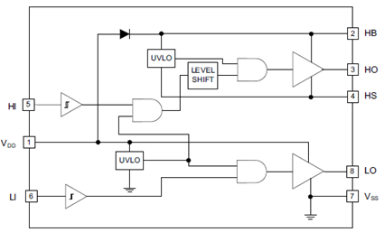
图1.UCC27201A-Q1功能框图
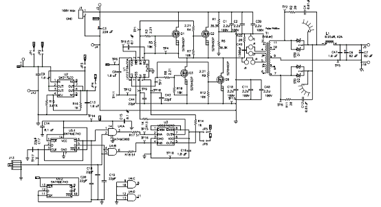
图2.UCC27201A-Q1开环半桥转换器电路
TIDA-00281汽车48V 1kW BLDC马达驱动参考设计
The TIDA-00281 TI Design is a 3-Phase Brushless DC Motor Drive designed to operate in 48-V automotive applications. The board is designed to drive motors in the 1-kW range and can handle currents up to 30-A. The design includes analog circuits working in conjunction with a C2000 LaunchPad to spin a 3-Phase BLDC motor without the need for position feedback from Hall Effect sensors or quadrature encoder.
TIDA-00281参考设计主要特性:
• Speed Control of 3-Phase Brushless DC (BLDC)Motors With no Position Sensors Needed
• Phase Voltage and Current Sensing Scaled andFiltered Feedback for Control of 3-Phase Power
• Operates Over Wide Range of Voltages From48-V Battery System
• Protection Against Overvoltage, Undervoltage,Overtemperature, Overcurrent, and TransientFaults
• Reverse Polarity Protection on 12-V Battery
• Isolated CAN Interface Connects to AutomotiveNetworks on 12-V Battery System
• Critical Components Fit in a 5-inch DiameterCircular PCB
• Components Selected for AutomotiveTemperature and Quality
• Test Points Provide Easy Access to Key MotorSignals
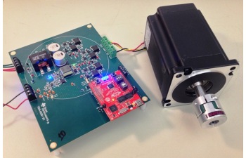
图3.TIDA-00281汽车48V 1kW BLDC马达驱动参考设计外形图
TIDA-00281参考设计应用:
• Water Pump
• eTurbo
• Radiator Fan
• HVAC Blower
• Oil Pump
TIDA-00281参考设计系统指标:
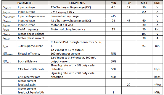
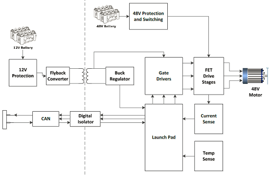
图4.TIDA-00281参考设计概述图
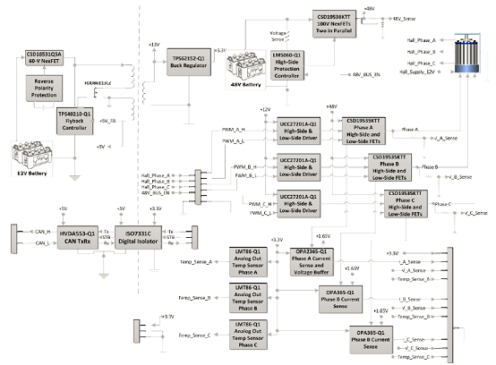
图5.TIDA-00281参考设计框图
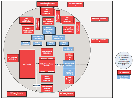
图6.TIDA-00281参考设计板简化平面图
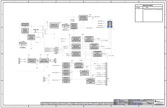
图7.TIDA-00281参考设计板电路图(1)
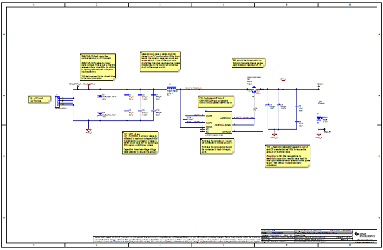
图8.TIDA-00281参考设计板电路图(2)
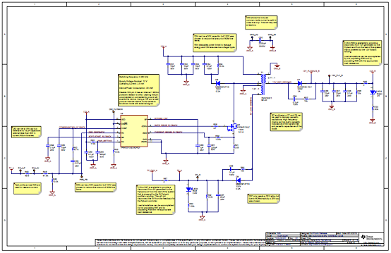
图9.TIDA-00281参考设计板电路图(3)
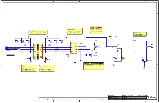
图10.TIDA-00281参考设计板电路图(4)
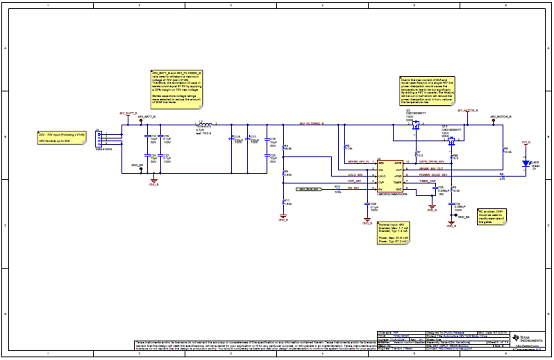
图11.TIDA-00281参考设计板电路图(5)
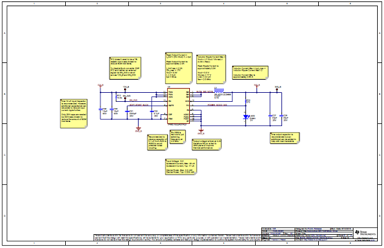
图12.TIDA-00281参考设计板电路图(6)
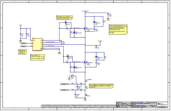
图13.TIDA-00281参考设计板电路图(7)
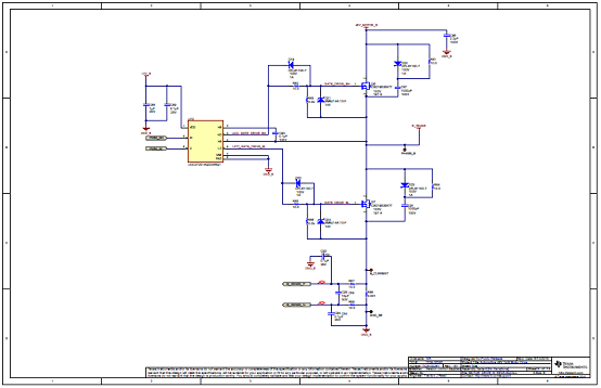
图14.TIDA-00281参考设计板电路图(8)
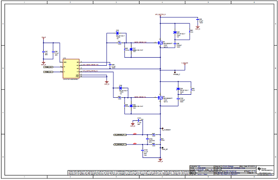
图15.TIDA-00281参考设计板电路图(9)
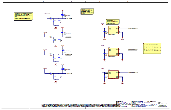
图16.TIDA-00281参考设计板电路图(10)
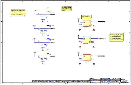
图17.TIDA-00281参考设计板电路图(11)
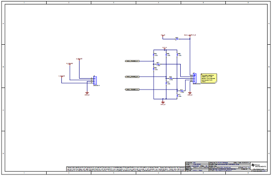
图18.TIDA-00281参考设计板电路图(12)
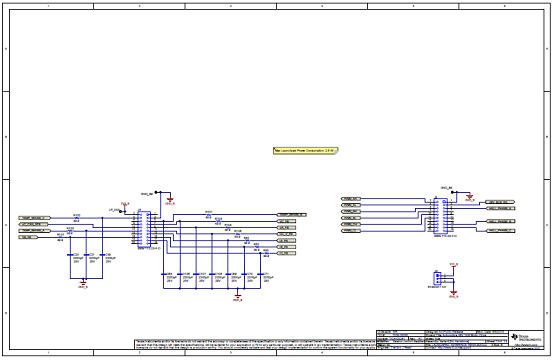
图19.TIDA-00281参考设计板电路图(13)
TIDA-00281参考设计板材料清单:
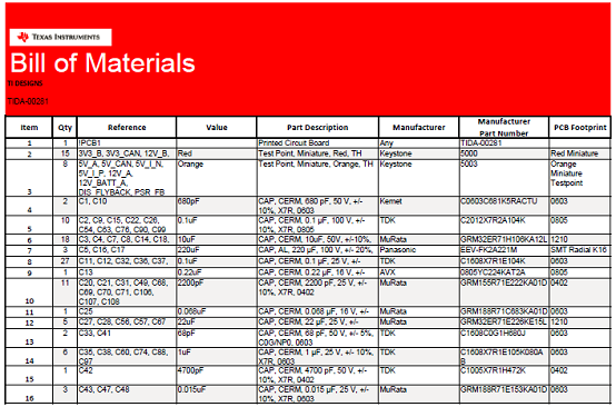
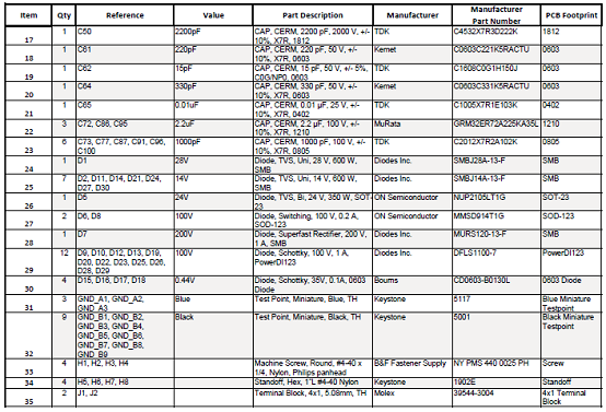
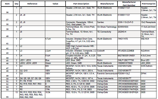
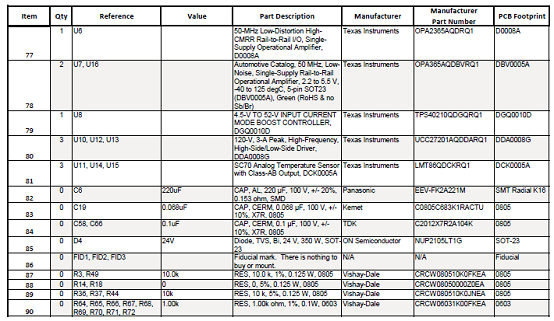
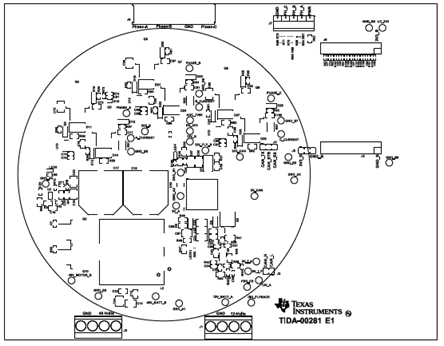
图20.TIDA-00281参考设计板PCB设计图(1)
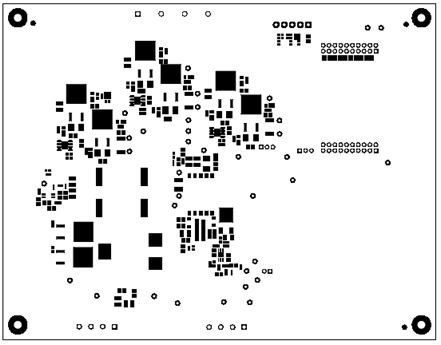
图21.TIDA-00281参考设计板PCB设计图(2)
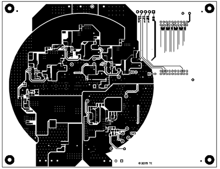
图22.TIDA-00281参考设计板PCB设计图(3)
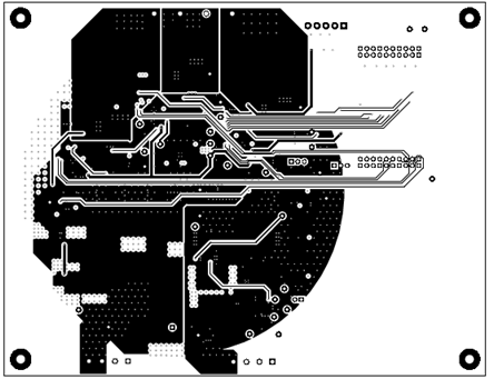
图23.TIDA-00281参考设计板PCB设计图(4)
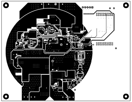
图24.TIDA-00281参考设计板PCB设计图(5)
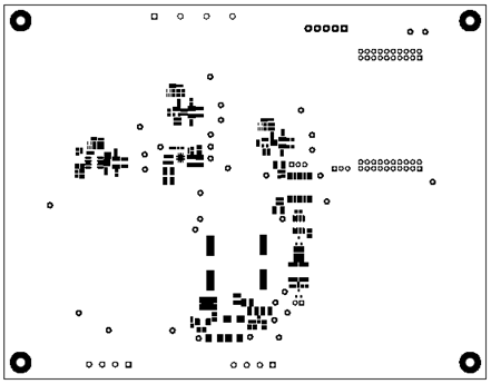
图25.TIDA-00281参考设计板PCB设计图(6)
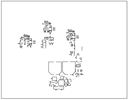
图26.TIDA-00281参考设计板PCB设计图(7)
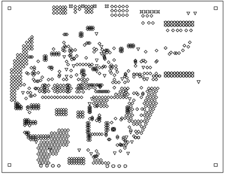
图27.TIDA-00281参考设计板PCB设计图(8)
The UCC27201A-Q1 high frequency N-Channel MOSFET driver includes a 120-V bootstrap diode and high-side/low-side driver with independent inputs for maximum control flexibility. This allows for N-Channel MOSFET control in half-bridge, full-bridge, two-switch forward and active clamp forward converters. The low-side and the high-side gate drivers are independently controlled and matched to 1-ns between the turn-on and turn-off of each other. The UCC27201A-Q1 is based on the popular UCC27200 and UCC27201 drivers, but offer some enhancements. In order to improve performance in noisy power supply environments the UCC27201A-Q1 has the ability to withstand a maximum of -18 V on its HS pin.
An on-chip bootstrap diode eliminates the external discrete diodes. Under-voltage lockout is provided for both the high-side and the low-side drivers forcing the outputs low if the drive voltage is below the specified threshold.
The UCC27201A-Q1 has TTL-compatible thresholds and is offered in a 10-Pin VSON and an 8-pin SOIC with a thermal pad.
UCC27201A-Q1主要特性:
Qualified for Automotive Applications
AEC-Q100 Qualified With the Following Results:
Device Temperature Grade 1: –40℃ to 140℃ Ambient Operating Temperature Range
Device HBM Classification Level 1C
Device CDM Classification Level C3
Negative Voltage Handling on HS (–18 V)
Drives Two N-Channel MOSFETs in High-Side/Low-Side Configuration
Maximum Boot Voltage: 120 V
Maximum VDD Voltage: 20 V
On-Chip 0.65-V VF, 0.6-Ω RD Bootstrap Diode
Greater than 1 MHz of Operation
20-ns Propagation Delay Times
3-A Sink, 3-A Source Output Currents
8-ns Rise and 7-ns Fall Time with 1000-pF Load
1-ns Delay Matching
Under Voltage Lockout for High-Side and Low-Side Driver
Offered in 8-Pin PowerPad SOIC-8 (DDA) and 10-Pin VSON (DMK) Packages
UCC27201A-Q1应用:
Auxiliary Inverters
DC-to-DC Converters for Power Train
Switch Mode Power Supplies
Motor Control
Half-Bridge Applications and Full-Bridge Converters
Two-Switch Forward Converters
Active-Clamp Forward Converters
High Voltage Synchronous-Buck Converters
Class-D Audio Amplifiers

图1.UCC27201A-Q1功能框图

图2.UCC27201A-Q1开环半桥转换器电路
TIDA-00281汽车48V 1kW BLDC马达驱动参考设计
The TIDA-00281 TI Design is a 3-Phase Brushless DC Motor Drive designed to operate in 48-V automotive applications. The board is designed to drive motors in the 1-kW range and can handle currents up to 30-A. The design includes analog circuits working in conjunction with a C2000 LaunchPad to spin a 3-Phase BLDC motor without the need for position feedback from Hall Effect sensors or quadrature encoder.
TIDA-00281参考设计主要特性:
• Speed Control of 3-Phase Brushless DC (BLDC)Motors With no Position Sensors Needed
• Phase Voltage and Current Sensing Scaled andFiltered Feedback for Control of 3-Phase Power
• Operates Over Wide Range of Voltages From48-V Battery System
• Protection Against Overvoltage, Undervoltage,Overtemperature, Overcurrent, and TransientFaults
• Reverse Polarity Protection on 12-V Battery
• Isolated CAN Interface Connects to AutomotiveNetworks on 12-V Battery System
• Critical Components Fit in a 5-inch DiameterCircular PCB
• Components Selected for AutomotiveTemperature and Quality
• Test Points Provide Easy Access to Key MotorSignals

图3.TIDA-00281汽车48V 1kW BLDC马达驱动参考设计外形图
TIDA-00281参考设计应用:
• Water Pump
• eTurbo
• Radiator Fan
• HVAC Blower
• Oil Pump
TIDA-00281参考设计系统指标:


图4.TIDA-00281参考设计概述图

图5.TIDA-00281参考设计框图

图6.TIDA-00281参考设计板简化平面图

图7.TIDA-00281参考设计板电路图(1)

图8.TIDA-00281参考设计板电路图(2)

图9.TIDA-00281参考设计板电路图(3)

图10.TIDA-00281参考设计板电路图(4)

图11.TIDA-00281参考设计板电路图(5)

图12.TIDA-00281参考设计板电路图(6)

图13.TIDA-00281参考设计板电路图(7)

图14.TIDA-00281参考设计板电路图(8)

图15.TIDA-00281参考设计板电路图(9)

图16.TIDA-00281参考设计板电路图(10)

图17.TIDA-00281参考设计板电路图(11)

图18.TIDA-00281参考设计板电路图(12)

图19.TIDA-00281参考设计板电路图(13)
TIDA-00281参考设计板材料清单:


图20.TIDA-00281参考设计板PCB设计图(1)

图21.TIDA-00281参考设计板PCB设计图(2)

图22.TIDA-00281参考设计板PCB设计图(3)

图23.TIDA-00281参考设计板PCB设计图(4)

图24.TIDA-00281参考设计板PCB设计图(5)

图25.TIDA-00281参考设计板PCB设计图(6)

图26.TIDA-00281参考设计板PCB设计图(7)

图27.TIDA-00281参考设计板PCB设计图(8)
|
||||||
|
||||||


