当前位置:首 页 --> 方案设计
NXP 33HB2001 10A H桥SPI编程无刷马达驱动方案
发布时间:2016/4/22 11:28:00 来源:
NXP公司的33HB2001是SMARTMOS单片10A H桥驱动集成电路,具有SPI可配置性和诊断功能,峰值电流大于10A,正常连续电流为3.0A,工作电压5.0 V - 28 V,具有超温保护,欠压保护和短路保护.本文介绍了33HB2001主要特性,功能框图,典型应用电路以及评估板FRDM-HB2001-EVM主要特性,框图和电路图,材料清单和PCB图.
The 33HB2001 is a SMARTMOS monolithic H-Bridge Power IC, enhanced with SPI configurability and diagnostic capabilities. It is designed primarily for DC motor or servo motor control applications within the specified current and voltage limits.
The 33HB2001 is able to control inductive loads with peak currents greater than 10 A. The nominal continuous average load current is 3.0 A. A current mirror output provides an analog feedback signal proportional to the load current.
This part is designed to specifically address the ISO 26262 safety requirements.
33HB2001主要特性:
•Advanced diagnostic reporting via a serial peripheral interface (SPI): charge pump undervoltage, overvoltage, and undervoltage on VPWR, short to ground and short to VPWR for each output, open load, temperature warning, and overtemperature shutdown
•Thermal management: Excellent thermal resistance of <1.0℃/W between junction and case (exposed pad)
•Eight selectable slew rates via the SPI: 0.25 V/s to more than 16 V/s for EMI and thermal performance optimization
•Four selectable current limits via the SPI: 5.4/7.0/8.8/10.7 A covering a wide range of applications
•Can be operated without SPI with default slew rate of 2.0 V/s and a 7.0 A current limit threshold
•Highly accurate real-time current feedback through a current mirror output signal with less than 5.0% error
•Drives inductive loads in a full H-Bridge or Half-bridge configuration
•Overvoltage protection places the load in high-side recirculation (braking) mode with notification in H-Bridge mode
•Wide operating range: 5.0 V to 28 V operation
•Low RDS(on) integrated MOSFETs: Maximum of 125 m (TJ = 150℃) for each MOSFET
•Internal protection for overtemperature, undervoltage, and short-circuit by signaling the error condition and disabling the outputs
•I/0 Pins can withstand up to 36 V
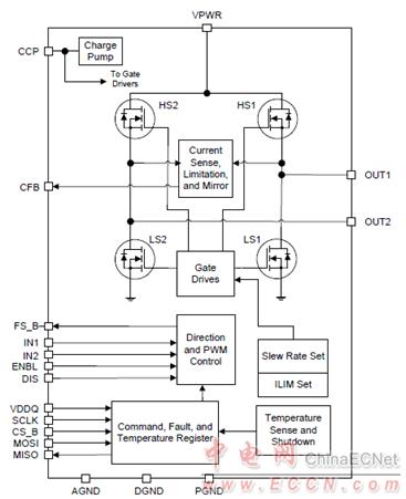
图1.33HB2001框图
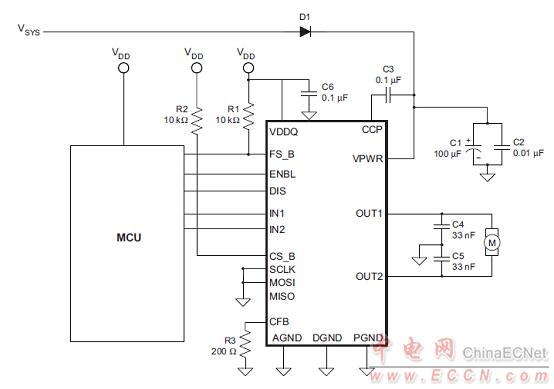
图2. 33HB2001简化应用电路图
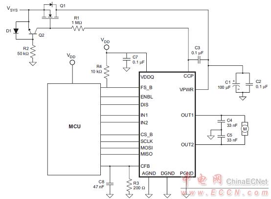
图3. 33HB2001典型应用电路图
评估板FRDM-HB2001-EVM
This evaluation kit is intended for use of ENGINEERING DEVELOPMENT OR EVALUATION PURPOSES ONLY. It is provided as a sample IC pre-soldered to a printed circuit board to make it easier to access inputs, outputs, and supply terminals. This evaluation board may be used with any development system or other source of I/O signals by simply connecting it to the host MCU or computer board via off-the-shelf cables. This evaluation board is not a Reference Design and is not intended to represent a final design recommendation for any particular application. Final device in an application will be heavily dependent on proper printed circuit board layout and heat sinking design as well as attention to supply filtering, transient suppression, and I/O signal quality.
The FRDM-HB2001-EVM evaluation kit exercises all the functions of the MC33HB2001 H-Bridge device. The parallel input can be easily controlled by lab equipment or any MCU with GPIOs. The board can be used in conjunction with a FRDM-KL25Z board connected to a PC’s USB port. Configure, control, and monitor the status of MC33HB2001 by using the board’s SPI communication capabilities.
评估板FRDM-HB2001-EVM主要特性:
The FRDM-HB2001-EVM board evaluates the NXP part MC33HB2001, including all functions. The board features the following:
• Built-in reverse battery protection
• Test points allows probing its signals
• Built-in voltage regulator to supply logic level circuitry
• LEDs to indicate the supply status and the direction of the motor
• Low Equivalent Series Resistance (ESR) capacitor to reduce ripple in the power supply
• Transient voltage suppressor to handle system level transients
评估板FRDM-HB2001-EVM包括:
•Assembled and tested evaluation board/module in anti-static bag
•FRDM-KL25Z
•Warranty card
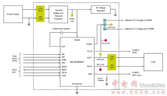
图4.评估板FRDM-HB2001-EVM框图
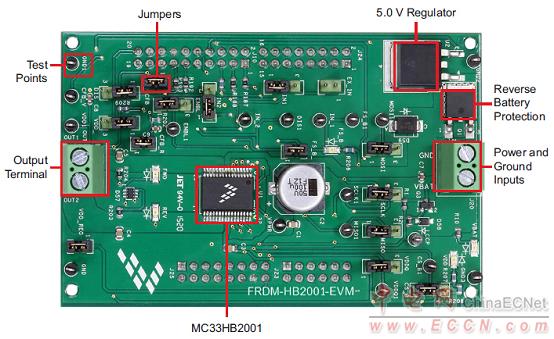
图5.评估板FRDM-HB2001-EVM外形图
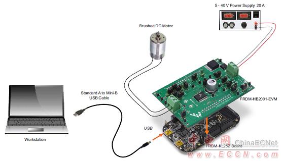
图6.评估板FRDM-HB2001-EVM和FRDM-KL25Z连接配置图
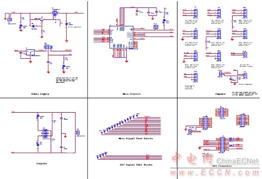
图7.评估板FRDM-HB2001-EVM电路图
评估板FRDM-HB2001-EVM材料清单:
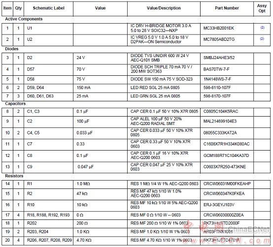
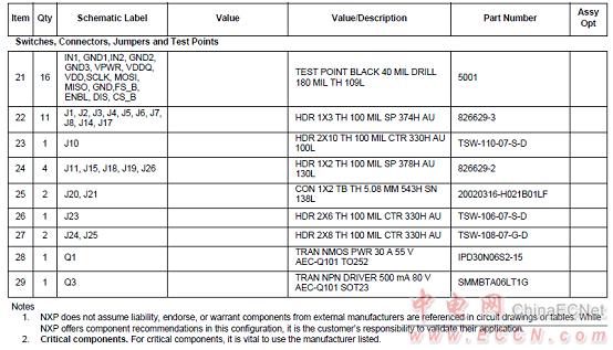
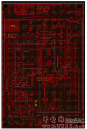
图8.评估板FRDM-HB2001-EVM PCB丝印图
The 33HB2001 is a SMARTMOS monolithic H-Bridge Power IC, enhanced with SPI configurability and diagnostic capabilities. It is designed primarily for DC motor or servo motor control applications within the specified current and voltage limits.
The 33HB2001 is able to control inductive loads with peak currents greater than 10 A. The nominal continuous average load current is 3.0 A. A current mirror output provides an analog feedback signal proportional to the load current.
This part is designed to specifically address the ISO 26262 safety requirements.
33HB2001主要特性:
•Advanced diagnostic reporting via a serial peripheral interface (SPI): charge pump undervoltage, overvoltage, and undervoltage on VPWR, short to ground and short to VPWR for each output, open load, temperature warning, and overtemperature shutdown
•Thermal management: Excellent thermal resistance of <1.0℃/W between junction and case (exposed pad)
•Eight selectable slew rates via the SPI: 0.25 V/s to more than 16 V/s for EMI and thermal performance optimization
•Four selectable current limits via the SPI: 5.4/7.0/8.8/10.7 A covering a wide range of applications
•Can be operated without SPI with default slew rate of 2.0 V/s and a 7.0 A current limit threshold
•Highly accurate real-time current feedback through a current mirror output signal with less than 5.0% error
•Drives inductive loads in a full H-Bridge or Half-bridge configuration
•Overvoltage protection places the load in high-side recirculation (braking) mode with notification in H-Bridge mode
•Wide operating range: 5.0 V to 28 V operation
•Low RDS(on) integrated MOSFETs: Maximum of 125 m (TJ = 150℃) for each MOSFET
•Internal protection for overtemperature, undervoltage, and short-circuit by signaling the error condition and disabling the outputs
•I/0 Pins can withstand up to 36 V

图1.33HB2001框图

图2. 33HB2001简化应用电路图

图3. 33HB2001典型应用电路图
评估板FRDM-HB2001-EVM
This evaluation kit is intended for use of ENGINEERING DEVELOPMENT OR EVALUATION PURPOSES ONLY. It is provided as a sample IC pre-soldered to a printed circuit board to make it easier to access inputs, outputs, and supply terminals. This evaluation board may be used with any development system or other source of I/O signals by simply connecting it to the host MCU or computer board via off-the-shelf cables. This evaluation board is not a Reference Design and is not intended to represent a final design recommendation for any particular application. Final device in an application will be heavily dependent on proper printed circuit board layout and heat sinking design as well as attention to supply filtering, transient suppression, and I/O signal quality.
The FRDM-HB2001-EVM evaluation kit exercises all the functions of the MC33HB2001 H-Bridge device. The parallel input can be easily controlled by lab equipment or any MCU with GPIOs. The board can be used in conjunction with a FRDM-KL25Z board connected to a PC’s USB port. Configure, control, and monitor the status of MC33HB2001 by using the board’s SPI communication capabilities.
评估板FRDM-HB2001-EVM主要特性:
The FRDM-HB2001-EVM board evaluates the NXP part MC33HB2001, including all functions. The board features the following:
• Built-in reverse battery protection
• Test points allows probing its signals
• Built-in voltage regulator to supply logic level circuitry
• LEDs to indicate the supply status and the direction of the motor
• Low Equivalent Series Resistance (ESR) capacitor to reduce ripple in the power supply
• Transient voltage suppressor to handle system level transients
评估板FRDM-HB2001-EVM包括:
•Assembled and tested evaluation board/module in anti-static bag
•FRDM-KL25Z
•Warranty card

图4.评估板FRDM-HB2001-EVM框图

图5.评估板FRDM-HB2001-EVM外形图

图6.评估板FRDM-HB2001-EVM和FRDM-KL25Z连接配置图

图7.评估板FRDM-HB2001-EVM电路图
评估板FRDM-HB2001-EVM材料清单:


图8.评估板FRDM-HB2001-EVM PCB丝印图
|
||||||
|
||||||


