当前位置:首 页 --> 方案设计
MTS2916A双极步进马达驱动方案
发布时间:2015/9/23 15:16:00 来源:
Microchip公司的MTS2916A是双极马达驱动器,也能双向控制两个DC马达,两个单独的H桥输出提供电压40V,连续电流750mA,主要用在步进马达,DC马达,汽车HVAC和座位控制.本文介绍了MTS2916A主要特性,框图和应用电路,以及评估板ADM00308主要特性,电路图,材料清单和PCB设计文件.
The MTS2916A motor driver is a CMOS devicecapable of driving both windings of a bipolar steppermotor or bidirectionally control two DC motors. Each ofthe two independent H-bridge outputs is capable ofsustaining 40V and delivering up to 750 mA of
continuous current. The output current level iscontrolled by an internal pulse-width modulation(PWM) circuit that is configured using two logic inputs,a current sense resistor and a selectable referencevoltage. The H-bridge outputs have been optimized toprovide a low output saturation voltage drop.
Full, half, and micro-stepping operations are possiblewith the PWM current control and logic inputs. Themaximum output current is set by a sensing resistorand a user selectable reference voltage. The outputcurrent limit is selected using two logic level inputs. Theselectable output current limits are 0%, 33%, 67%, or100% of the maximum output current. Each bridge hasa PHASE input signal which is used to control the directionof current flow through the H-bridge and the load.
The H-bridge power stage is controlled by non-overlappingsignals which prevent current cross conductionwhen switching the direction of the current flow. Internalclamp diodes protect against inductive transients.
Thermal protection circuitry disables the outputs whenthe junction temperature exceeds the safe operatinglimit. No special power-up sequencing is required.
Undervoltage Lockout circuitry prevents the chip fromoperating when the load supply is applied prior to thelogic supply.
The device is supplied in a 24-pin SOP package.
MTS2916A主要特性:
• 750 mA Continuous Output Current
• Load Voltage Supply: 10V to 40V
• Full Bipolar Stepper Motor Drive Capability
• Bidirectional DC Motor Capability
• Internal Fixed TOFF Time PWM Current Control
• Internal Protection Diodes
• Internal Thermal Shutdown
• Under Voltage Lockout
• LS-TTL Compatible Logic Inputs with Pull-UpResistors
• Low RON Output Resistance
• Low Quiescent Current
• Operating Temperature Range: -40℃ to +105℃
• Pin Compatible with Allegro 2916
MTS2916A应用:
• Stepper Motor Actuators
• DC Motor Actuators
• Automotive HVAC Ventilation
• Automotive Power Seats
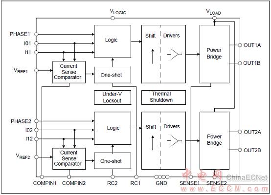
图1. MTS2916A框图
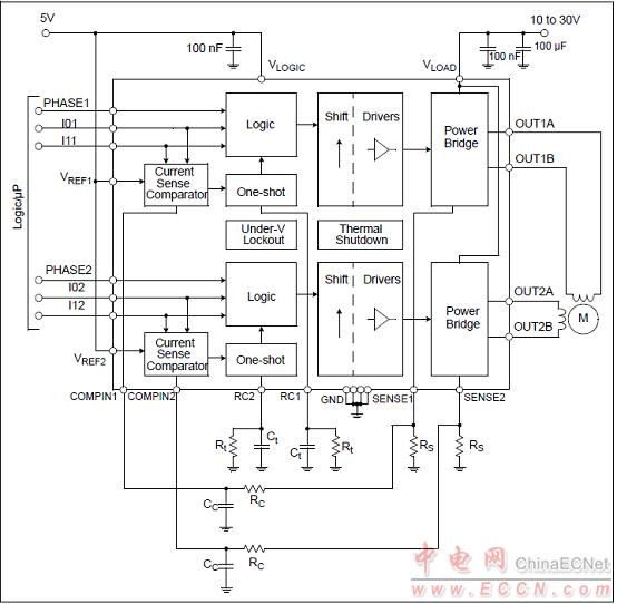
图2. MTS2916A典型应用框图
MTS2916A双全桥步进马达评估板ADM00308
The MTS2916A Dual Full-Bridge Stepper Motor Driver Evaluation Board demonstrates the capabilities of the MTS2916A to control both windings of a bipolar stepper motor. The board also demonstrates the capabilities of the MTS62C19A, which has the same functionality, but different pin assignments. A PIC16F883 is utilized for motor control processing.
This evaluation board incorporates features through the implementation of push button switches and a variable speed input potentiometer to exercise a stepper motor in Full-Step, Half-Step, Modified Half-Step and Microstepping modes. LEDs indicate a binary representation of which mode has been selected. The evaluation board and the stepper motor can be powered from a single power input J1 (7 VDC to 12 VDC) with jumper JP2 installed. For higher motor voltages, make sure JP2 is not installed, and connect VLOAD at J4. Numerous test points have been designed into the board to allow easy access.
MTS2916A评估板ADM00308主要特性:
Push Button mode, Run, Hold and Direction control
Potentiometer variable speed adjustment
LED mode indication
Maximum winding current with the combination of Rs, VREF and conditioning of I0/I1 logic inputs
PICkit™ Programming connector (J5) to implement user-created code
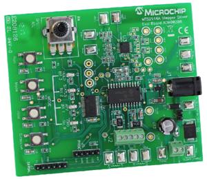
图3.评估板ADM00308外形图
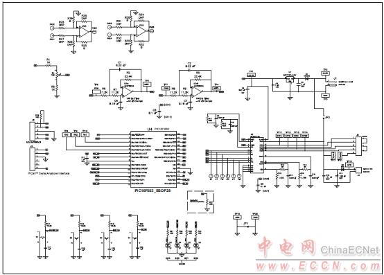
图4.评估板ADM00308电路图
评估板ADM00308材料清单:
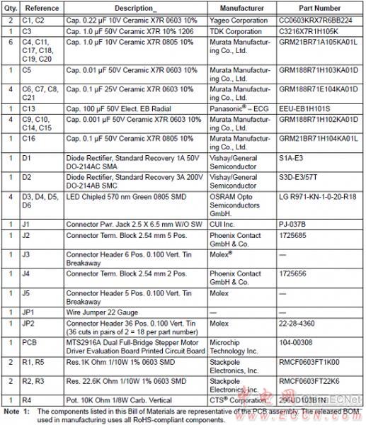
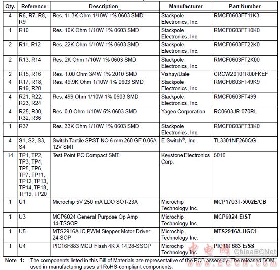
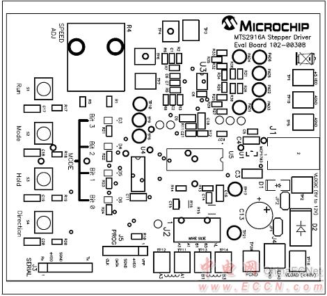
图5.评估板ADM00308 PCB设计图(1)
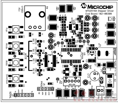
图6.评估板ADM00308 PCB设计图(2)
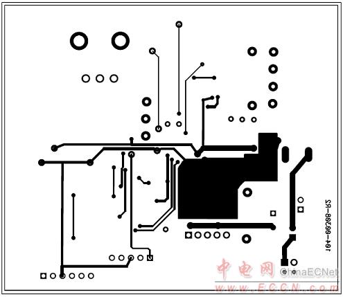
图7.评估板ADM00308 PCB设计图(3)
The MTS2916A motor driver is a CMOS devicecapable of driving both windings of a bipolar steppermotor or bidirectionally control two DC motors. Each ofthe two independent H-bridge outputs is capable ofsustaining 40V and delivering up to 750 mA of
continuous current. The output current level iscontrolled by an internal pulse-width modulation(PWM) circuit that is configured using two logic inputs,a current sense resistor and a selectable referencevoltage. The H-bridge outputs have been optimized toprovide a low output saturation voltage drop.
Full, half, and micro-stepping operations are possiblewith the PWM current control and logic inputs. Themaximum output current is set by a sensing resistorand a user selectable reference voltage. The outputcurrent limit is selected using two logic level inputs. Theselectable output current limits are 0%, 33%, 67%, or100% of the maximum output current. Each bridge hasa PHASE input signal which is used to control the directionof current flow through the H-bridge and the load.
The H-bridge power stage is controlled by non-overlappingsignals which prevent current cross conductionwhen switching the direction of the current flow. Internalclamp diodes protect against inductive transients.
Thermal protection circuitry disables the outputs whenthe junction temperature exceeds the safe operatinglimit. No special power-up sequencing is required.
Undervoltage Lockout circuitry prevents the chip fromoperating when the load supply is applied prior to thelogic supply.
The device is supplied in a 24-pin SOP package.
MTS2916A主要特性:
• 750 mA Continuous Output Current
• Load Voltage Supply: 10V to 40V
• Full Bipolar Stepper Motor Drive Capability
• Bidirectional DC Motor Capability
• Internal Fixed TOFF Time PWM Current Control
• Internal Protection Diodes
• Internal Thermal Shutdown
• Under Voltage Lockout
• LS-TTL Compatible Logic Inputs with Pull-UpResistors
• Low RON Output Resistance
• Low Quiescent Current
• Operating Temperature Range: -40℃ to +105℃
• Pin Compatible with Allegro 2916
MTS2916A应用:
• Stepper Motor Actuators
• DC Motor Actuators
• Automotive HVAC Ventilation
• Automotive Power Seats

图1. MTS2916A框图

图2. MTS2916A典型应用框图
MTS2916A双全桥步进马达评估板ADM00308
The MTS2916A Dual Full-Bridge Stepper Motor Driver Evaluation Board demonstrates the capabilities of the MTS2916A to control both windings of a bipolar stepper motor. The board also demonstrates the capabilities of the MTS62C19A, which has the same functionality, but different pin assignments. A PIC16F883 is utilized for motor control processing.
This evaluation board incorporates features through the implementation of push button switches and a variable speed input potentiometer to exercise a stepper motor in Full-Step, Half-Step, Modified Half-Step and Microstepping modes. LEDs indicate a binary representation of which mode has been selected. The evaluation board and the stepper motor can be powered from a single power input J1 (7 VDC to 12 VDC) with jumper JP2 installed. For higher motor voltages, make sure JP2 is not installed, and connect VLOAD at J4. Numerous test points have been designed into the board to allow easy access.
MTS2916A评估板ADM00308主要特性:
Push Button mode, Run, Hold and Direction control
Potentiometer variable speed adjustment
LED mode indication
Maximum winding current with the combination of Rs, VREF and conditioning of I0/I1 logic inputs
PICkit™ Programming connector (J5) to implement user-created code

图3.评估板ADM00308外形图

图4.评估板ADM00308电路图
评估板ADM00308材料清单:


图5.评估板ADM00308 PCB设计图(1)

图6.评估板ADM00308 PCB设计图(2)

图7.评估板ADM00308 PCB设计图(3)
|
||||||
|
||||||


